Which of the following statements about hard and soft iron in relation to ? [ Result LAPL ]
Question 48-1 : Hard iron magnetism is of a permanent nature and soft iron is of a non permanent nature both hard and soft hard iron are of a permanent nature both hard and soft iron are of a non permanent nature hard iron is of a non permanent nature and soft iron is of a permanent nature
 Hard iron magnetism is of a permanent nature and soft iron is of a non-permanent nature.
 The turning error of a direct reading magnetic compass ?
Question 48-2 : Increases when the magnetic latitude increases decreases when the magnetic latitude increases does not depend on the magnetic latitude decreases when the magnetic longitude increases
 Increases when the magnetic latitude increases.
 Direct reading magnetic compass errors are ?
Question 48-3 : Due to north change depending on the bank angle and magnetic heading due to the lateral gusts which occur when the aircraft is heading eastward or westward due to schuler oscillations parallax errors due to compass rose oscillations
 Due to north change, depending on the bank angle and magnetic heading.
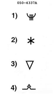
 The flux valve of a gyromagnetic compass .1 feeds the error detector.2 feeds ?
Question 48-4 : 1 3 1 2 2 3 3
 1, 3.
1, 3. A flux valve ?
Question 48-5 : Is usually located in the wing tip to avoid as much as possible magnetic disturbances of the airplane is a symetrical system located in each wingtip giving an average information less disturbed by the airplane structure is located in the wing tip to avoid vibrations is located along the fuselage aligned with airplane axis
 Is usually located in the wing tip, to avoid as much as possible magnetic disturbances of the airplane.
 An electromagnet is a type of magnet in which ?
Question 48-6 : The magnetic field is produced by the flow of an electric current the magnetic field is permanent no electric force is required a solenoid wire is coiled over permanent magnet
 The magnetic field is produced by the flow of an electric current.
 The inclination of the earth magnetic field at the magnetic equator is equal to ?
Question 48-7 : 0° 45° 90° 180°
 0°.
0°. The earth's north magnetic pole ?
Question 48-8 : Is located approximately in northern canada is located in russia coincide with geographical north coincide with true north
 Is located approximately in northern canada.
 In the northern hemisphere during acceleration in a westerly heading a direct ?
Question 48-9 : Indicates an apparent turn to the north indicates an apparent turn to the south is late compared to the rate of turn of the aircraft is in advance compared to the rate of turn of the aircraft
The principle of the compass swinging procedures is to ?
Question 48-10 : Determine the amount by which the compass readings are affected by hard and soft iron magnetism correct for deviation due to hard iron magnetism only correct for deviation due to soft iron magnetism only correct for deviation due to soft iron and hard iron magnetism
 Determine the amount by which the compass readings are affected by hard and soft iron magnetism.
 Which of these statements about fundamental laws of magnetism are correct or ?
Question 48-11 : 1 is incorrect 2 is incorrect 1 is correct 2 is incorrect 1 is correct 2 is correct 1 is incorrect 2 is correct
The force of attraction or repulsion between two magnets ?
Question 48-12 : Varies inversely as the square of the distance between them is independent of the distance between them since a compass is able to aligns itself everywhere on the surface of the earth is proportional to the distance between them can not be measured
 Varies inversely as the square of the distance between them.
 The magnetic poles are the two positions on the earth's surface where the lines ?
Question 48-13 : Are entirely vertical are entirely horizontal are at 45° are at 0°
 Are entirely vertical.
 The purpose of a magnetic compass compensation is to correct for ?
Question 48-14 : Deviations accelerations magnetic variation residual deviations
 Deviations.
 The purpose of a magnetic compass calibration is to ?
Question 48-15 : Determine the residual deviations determine the residual variation correct the residual deviations correct the residual variation
 Determine the residual deviations.
 The location of the earth's magnetic poles ?
Question 48-16 : Periodically wanders as much as 15 km every year periodically wanders as much as 100 km every year wanders twice a year wanders twice per decade
 Periodically wanders (as much as 15 km every year).
 Which of these statements about fundamental laws of magnetism are correct or ?
Question 48-17 : 1 is correct 2 is correct 1 is incorrect 2 is incorrect 1 is correct 2 is incorrect 1 is incorrect 2 is correct
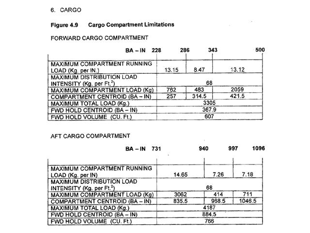 1 is correct, 2 is correct
 Which of these statements about the properties of a simple bar magnet are ?
Question 48-18 : 1 is correct 2 is correct 1 is incorrect 2 is incorrect 1 is incorrect 2 is correct 1 is correct 2 is incorrect
 1 is correct, 2 is correct.
 The magnetic variation at any point on the earth's surface is the angle ?
Question 48-19 : Between the horizontal component of the magnetic field and true north direction between the vertical component of the magnetic field and true north direction between the horizontal component of the magnetic field and magnetic north direction between the vertical component of the magnetic field and magnetic north direction
 Between the horizontal component of the magnetic field and true north direction.
 The magnetic variation ?
Question 48-20 : Is caused by the different locations of the geographic north pole and the magnetic north pole is equal to 180° at the magnetic equator is equal to 90° at the magnetic equator is caused by the different locations of the geographic north pole and the true north pole
 Is caused by the different locations of the geographic north pole and the magnetic north pole.
 The inclination of the earth's magnetic field at the north magnetic pole is ?
Question 48-21 : 90° 0° 45° 180°
 90°.
90°. Because of the earth's magnetic field a compass placed anywhere on earth will ?
Question 48-22 : North magnetic pole south magnetic pole geographic north pole geographic south pole
 North magnetic pole.
 Which of the following is an occasion for carrying out a compass swing on a ?
Question 48-23 : After an aircraft has passed through a severe electrical storm or has been struck by lightning before an aircraft goes on any flight that involves a large change of magnetic latitude after any of the aircraft radio equipment has been changed due to unserviceability whenever an aircraft carries a large freight load regardless of its content
 After an aircraft has passed through a severe electrical storm, or has been struck by lightning.
 The directive force of the earth's magnetic field ?
Question 48-24 : Is greatest at the magnetic equator increases as the magnetic variation increases increases as magnetic latitude increases varies with the heading of the aircraft
 Is greatest at the magnetic equator.
 The compass heading can be derived from the magnetic heading by reference to a ?
Question 48-25 : Compass swinging curve map showing the isoclinic lines deviation correction curve map showing the isogonal lines
 Compass swinging curve.
 The indications on a directional gyroscope are subject to errors the most ?
Question 48-26 : 1 2 3 5 2 3 5 3 4 5 1 2 4 5
 1, 2, 3, 5.
 Graphic at reference shows three gyro assemblies a b and c .among these gyros . ?
Question 48-27 : 1b 2c 3a 1c 2b 3a 1b 2a 3c 1a 2b 3c
 1b, 2c, 3a.
 When an aircraft has turned 360 degrees with a constant attitude and bank the ?
Question 48-28 : Attitude and bank correct too much nose up and bank too low too much nose up and bank correct too much nose up and bank too high
 Attitude and bank correct.
 When an aircraft has turned 90 degrees with a constant attitude and bank the ?
Question 48-29 : Too much nose up and bank too low too much nose up and bank too high too much nose up and bank correct attitude and bank correct
 Too much nose-up and bank too low.
 The gyroscope of a turn indicator has . nb the degree s of freedom of a gyro ?
Question 48-30 : 1 degree of freedom 3 degrees of freedom 2 degrees of freedom 0 degree of freedom
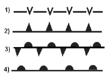 1 degree of freedom.
 The indication of the directional gyro is valid only for a limited period of ?
Question 48-31 : 1 3 1 3 4 1 2 3 1 2 4
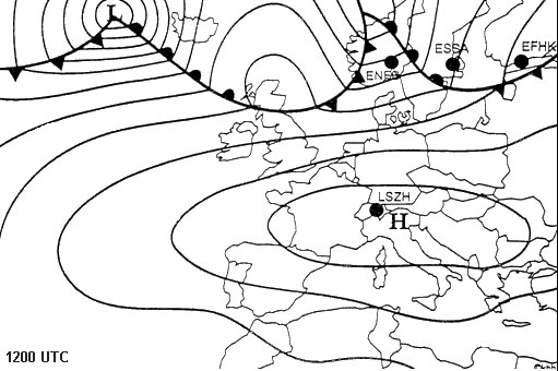 1, 3.
1, 3. An airborne instrument equipped with a gyro with 2 degrees of freedom and a ?
Question 48-32 : A directional gyro an artificial horizon a turn indicator a fluxgate compass
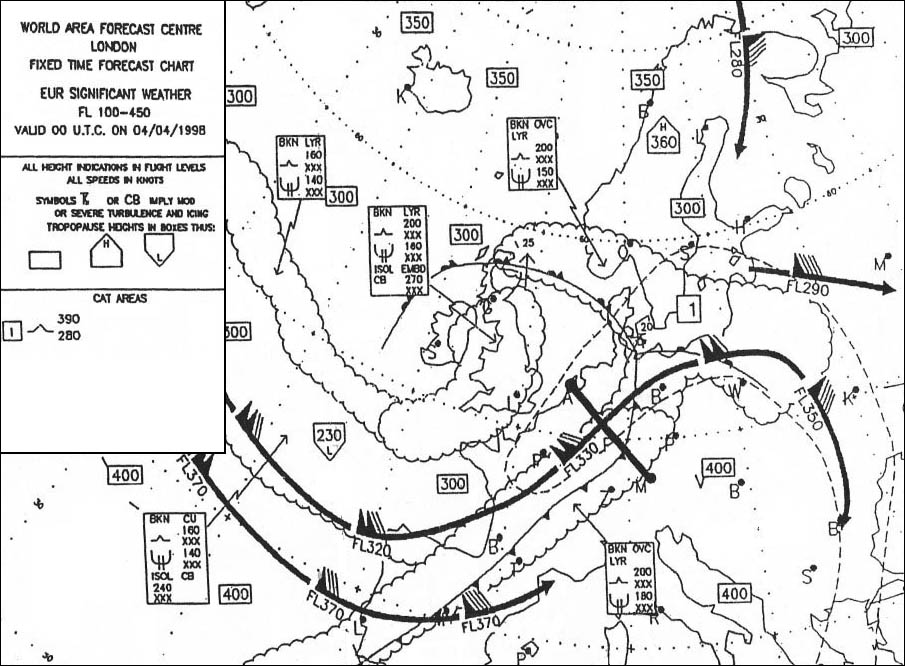 A directional gyro.
 An airborne instrument equipped with a gyro with 1 degree of freedom and a ?
Question 48-33 : Turn indicator gyromagnetic compass fluxgate compass directional gyro
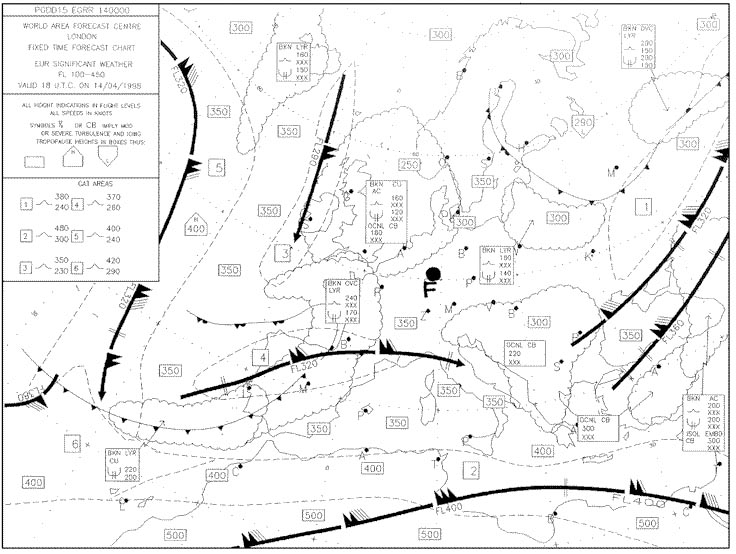 Turn indicator.
 In a turn at a constant angle of bank the turn indicator reading is ?
Question 48-34 : Inversely proportional to the aircraft true airspeed proportional to the aircraft true airspeed independent to the aircraft true airspeed proportional to the aircraft weight
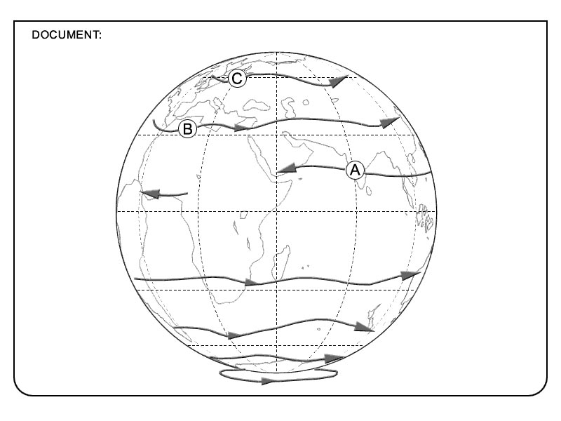 Inversely proportional to the aircraft true airspeed.
 At a low bank angle the measurement of rate of turn actually consists in ?
Question 48-35 : Yaw rate of the aircraft pitch rate of the aircraft roll rate of the aircraft bank of the aircraft
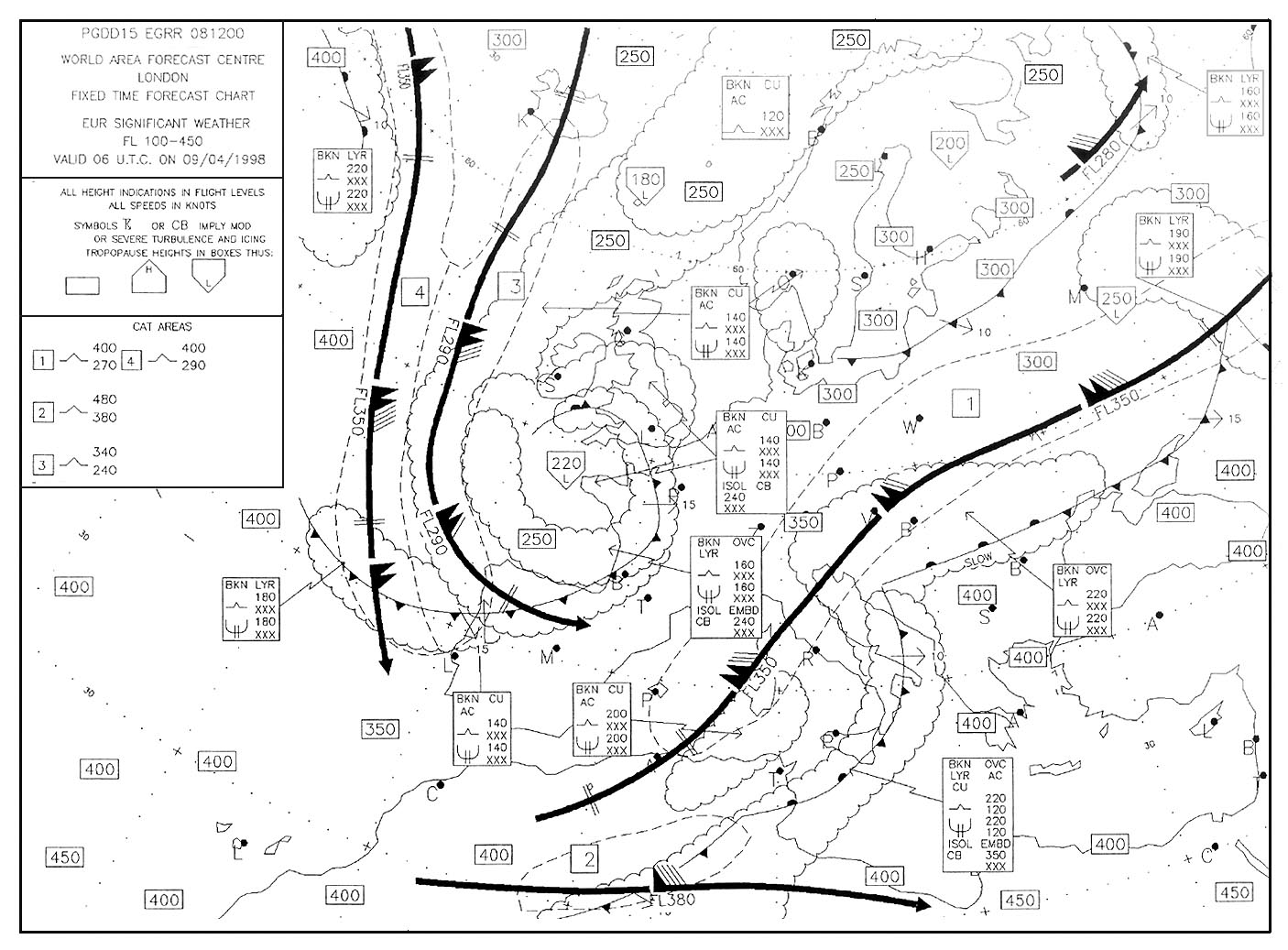 Yaw rate of the aircraft.
 The rate of turn is the ?
Question 48-36 : Change of heading rate of the aircraft yaw rate in a turn aircraft speed in a turn pitch rate in a turn
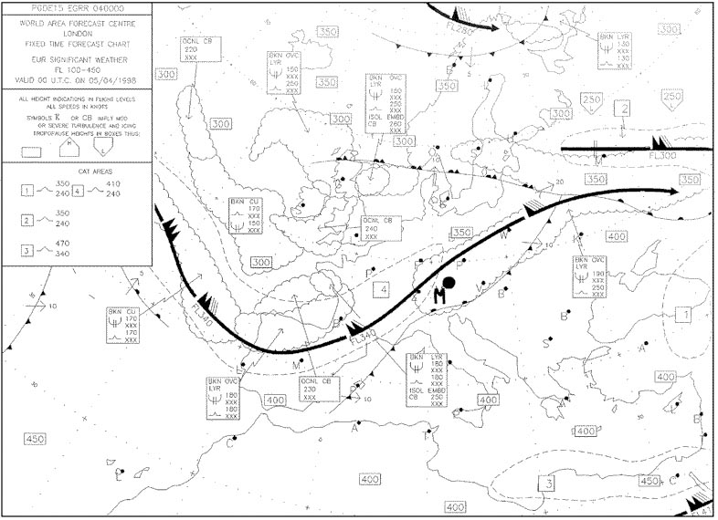 Change-of-heading rate of the aircraft.
 On the ground during a right turn the turn indicator indicates ?
Question 48-37 : Needle to the right ball to left needle to the right ball to right needle in the middle ball to right needle in the middle ball to left
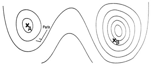 Needle to the right, ball to left
 On the ground during a left turn the turn indicator indicates ?
Question 48-38 : Needle to the left ball to the right needle to the left ball to the left needle in the middle ball to the right needle in the middle ball to the left
 Needle to the left, ball to the right.
 When in flight the needle and ball of a needle and ball indicator are on the ?
Question 48-39 : Turning left with too much bank turning left with not enough bank turning right with too much bank turning right with not enough bank
 Turning left with too much bank
 When in flight the needle and ball of a needle and ball indicator are on the ?
Question 48-40 : Turning right with too much bank turning right with not enough bank turning left with too much bank turning left with not enough bank
 Turning right with too much bank
 ~
Exclusive rights reserved. Reproduction prohibited under penalty of prosecution.
1879 Free Training Exam Other source study: Ppl exam examen 48
