Warning: Cannot modify header information - headers already sent by (output started at /home/webosapi/www/S_ATPL/lib_gestion.php:2868) in /home/webosapi/www/S_ATPL/lib_gestion.php on line 746
Un compte Premium offert sur le site FCL.055 ! Rendez-vous sur www.fcl055-exam.fr puis créez un compte avec le même email que celui...   [Lire la suite]


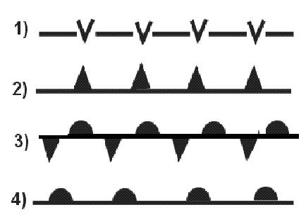
From the following fuselage profile sort them from the worst to the best one concerning the pressurization 818 ?

Admission > airport

exemple reponse 124
N°1 clearly weakest would only be used on an unpressurised aircraft (twin otter example) n°2 geometrically strongest from a pressurisation point of view as hoop stresses can be uniform on whole cross section n°3 'double bubble' type where two circles intersect connected via a floor not best choice but clearly better than n°4 n°4 pressurization constraints will not be optimal on an oval format this question also exists with statement 'from following fuselage profile sort them from worst to best one concerning pressurization ' answer 1 4 3 2.

Other study patent: Telepilote theorique examen 20

The illumination of the green landing gear light indicates that the landing gear is ?

exemple reponse 125
The illumination of green landing gear light indicates that landing gear N°1 clearly weakest would only be used on an unpressurised aircraft (twin otter example) n°2 geometrically strongest from a pressurisation point of view as hoop stresses can be uniform on whole cross section n°3 'double bubble' type where two circles intersect connected via a floor not best choice but clearly better than n°4 n°4 pressurization constraints will not be optimal on an oval format this question also exists with statement 'from following fuselage profile sort them from worst to best one concerning pressurization ' answer 1 4 3 2.

The damping element in a landing gear shock absorber used on large aircrafts is ?

exemple reponse 127
The damping element in a landing gear shock absorber used on large aircrafts N°1 clearly weakest would only be used on an unpressurised aircraft (twin otter example) n°2 geometrically strongest from a pressurisation point of view as hoop stresses can be uniform on whole cross section n°3 'double bubble' type where two circles intersect connected via a floor not best choice but clearly better than n°4 n°4 pressurization constraints will not be optimal on an oval format this question also exists with statement 'from following fuselage profile sort them from worst to best one concerning pressurization ' answer 1 4 3 2.

  • exemple reponse 128
    'nose wheel shimmy' may be described as A possibly damaging vibration of nose wheel when moving on ground. N°1 clearly weakest would only be used on an unpressurised aircraft (twin otter example) n°2 geometrically strongest from a pressurisation point of view as hoop stresses can be uniform on whole cross section n°3 'double bubble' type where two circles intersect connected via a floor not best choice but clearly better than n°4 n°4 pressurization constraints will not be optimal on an oval format this question also exists with statement 'from following fuselage profile sort them from worst to best one concerning pressurization ' answer 1 4 3 2.

  • exemple reponse 129
    The abs auto brake system being disconnected after landing A possibly damaging vibration of nose wheel when moving on ground. 1 auto brake disarm light illuminated (amber) speed brake lever moved to down detent during rto or landing manual brakes applied during rto or landing thrust lever(s) advanced during rto or landing except during first 3 seconds after touchdown landing landing made with rto selected rto mode selected on ground illuminates one to two seconds then extinguishes a malfunction exists in automatic braking system extinguished auto brake select switch set to off autobrake armed 2 auto brake select switch off autobrake system deactivated 1 2 3 or max selects desired deceleration rate landing switch must be pulled out to select max deceleration rto automatically applies maximum brake pressure when thrust levers are retarded to idle at or above 90 knots 3 antiskid inoperative (antiskid inop) light illuminated (amber) a system fault detected antiskid monitoring system extinguished antiskid system operating normally.

  • exemple reponse 130
    The purposes of oil and nitrogen in an oleo pneumatic strut are The oil supplies damping function the nitrogen supplies spring function. 1 auto brake disarm light illuminated (amber) speed brake lever moved to down detent during rto or landing manual brakes applied during rto or landing thrust lever(s) advanced during rto or landing except during first 3 seconds after touchdown landing landing made with rto selected rto mode selected on ground illuminates one to two seconds then extinguishes a malfunction exists in automatic braking system extinguished auto brake select switch set to off autobrake armed 2 auto brake select switch off autobrake system deactivated 1 2 3 or max selects desired deceleration rate landing switch must be pulled out to select max deceleration rto automatically applies maximum brake pressure when thrust levers are retarded to idle at or above 90 knots 3 antiskid inoperative (antiskid inop) light illuminated (amber) a system fault detected antiskid monitoring system extinguished antiskid system operating normally.

  • exemple reponse 131
    The highest load on torsion link in a bogie gear Whilst turning on ground with a small radius. 1 auto brake disarm light illuminated (amber) speed brake lever moved to down detent during rto or landing manual brakes applied during rto or landing thrust lever(s) advanced during rto or landing except during first 3 seconds after touchdown landing landing made with rto selected rto mode selected on ground illuminates one to two seconds then extinguishes a malfunction exists in automatic braking system extinguished auto brake select switch set to off autobrake armed 2 auto brake select switch off autobrake system deactivated 1 2 3 or max selects desired deceleration rate landing switch must be pulled out to select max deceleration rto automatically applies maximum brake pressure when thrust levers are retarded to idle at or above 90 knots 3 antiskid inoperative (antiskid inop) light illuminated (amber) a system fault detected antiskid monitoring system extinguished antiskid system operating normally.

  • Question 20-8

    The function of a fusible plug to Protect tyre against explosion due to excessive temperature. 1 auto brake disarm light illuminated (amber) speed brake lever moved to down detent during rto or landing manual brakes applied during rto or landing thrust lever(s) advanced during rto or landing except during first 3 seconds after touchdown landing landing made with rto selected rto mode selected on ground illuminates one to two seconds then extinguishes a malfunction exists in automatic braking system extinguished auto brake select switch set to off autobrake armed 2 auto brake select switch off autobrake system deactivated 1 2 3 or max selects desired deceleration rate landing switch must be pulled out to select max deceleration rto automatically applies maximum brake pressure when thrust levers are retarded to idle at or above 90 knots 3 antiskid inoperative (antiskid inop) light illuminated (amber) a system fault detected antiskid monitoring system extinguished antiskid system operating normally.

  • Question 20-9

    Compared to a tyre fitted with an inner tube a tubeless tyre presents following characteristics 1 high heating2 valve fragility3 lower risk of bursting4 better adjustment to wheelsthe combination containing all correct statements Protect tyre against explosion due to excessive temperature. 1 auto brake disarm light illuminated (amber) speed brake lever moved to down detent during rto or landing manual brakes applied during rto or landing thrust lever(s) advanced during rto or landing except during first 3 seconds after touchdown landing landing made with rto selected rto mode selected on ground illuminates one to two seconds then extinguishes a malfunction exists in automatic braking system extinguished auto brake select switch set to off autobrake armed 2 auto brake select switch off autobrake system deactivated 1 2 3 or max selects desired deceleration rate landing switch must be pulled out to select max deceleration rto automatically applies maximum brake pressure when thrust levers are retarded to idle at or above 90 knots 3 antiskid inoperative (antiskid inop) light illuminated (amber) a system fault detected antiskid monitoring system extinguished antiskid system operating normally.

  • Question 20-10

    An under inflated tyre will Experience increased wear at shoulders. 1 auto brake disarm light illuminated (amber) speed brake lever moved to down detent during rto or landing manual brakes applied during rto or landing thrust lever(s) advanced during rto or landing except during first 3 seconds after touchdown landing landing made with rto selected rto mode selected on ground illuminates one to two seconds then extinguishes a malfunction exists in automatic braking system extinguished auto brake select switch set to off autobrake armed 2 auto brake select switch off autobrake system deactivated 1 2 3 or max selects desired deceleration rate landing switch must be pulled out to select max deceleration rto automatically applies maximum brake pressure when thrust levers are retarded to idle at or above 90 knots 3 antiskid inoperative (antiskid inop) light illuminated (amber) a system fault detected antiskid monitoring system extinguished antiskid system operating normally.

  • Question 20-11

    A scissor torsion link a component found on landing gears its function to Prevent any rotation of oleo strut in landing gear shock absorber. The torque links prevent rotation about vertical axis to maintain wheel alignment in fore and aft direction throughout vertical range of oleo travel in maintaining proper wheel alignment torque links stabilize any torsional oscillations (shimmy) by their design torque links have their maximum mechanical advantage control when oleo compressed minimum advantage when oleo fully extended sometime it doesn't work .

  • Question 20-12

    Associate correct legend to each of numbered diagrams 841 cantilever 2 fork 3 half fork 4 dual wheels. The torque links prevent rotation about vertical axis to maintain wheel alignment in fore and aft direction throughout vertical range of oleo travel in maintaining proper wheel alignment torque links stabilize any torsional oscillations (shimmy) by their design torque links have their maximum mechanical advantage control when oleo compressed minimum advantage when oleo fully extended sometime it doesn't work .

  • Question 20-13

    The function of an accumulator in a hydraulic brake system To supply a limited amount of brake energy in event of failure of hydraulic system normally supplying brakes. The torque links prevent rotation about vertical axis to maintain wheel alignment in fore and aft direction throughout vertical range of oleo travel in maintaining proper wheel alignment torque links stabilize any torsional oscillations (shimmy) by their design torque links have their maximum mechanical advantage control when oleo compressed minimum advantage when oleo fully extended sometime it doesn't work .

  • Question 20-14

    A red or an amber light on an undercarriage position indicator signifies At least one wheel in travelling or unlocked condition. The torque links prevent rotation about vertical axis to maintain wheel alignment in fore and aft direction throughout vertical range of oleo travel in maintaining proper wheel alignment torque links stabilize any torsional oscillations (shimmy) by their design torque links have their maximum mechanical advantage control when oleo compressed minimum advantage when oleo fully extended sometime it doesn't work .

  • Question 20-15

    In some aircraft there a protection device to avoid landing gear being inadvertently retracted on ground it consists of A latch located in landing gear lever. The torque links prevent rotation about vertical axis to maintain wheel alignment in fore and aft direction throughout vertical range of oleo travel in maintaining proper wheel alignment torque links stabilize any torsional oscillations (shimmy) by their design torque links have their maximum mechanical advantage control when oleo compressed minimum advantage when oleo fully extended sometime it doesn't work .

  • Question 20-16

    Overcentre mechanisms in landing gear systems are used to Lock landing gear in up and/or down positions. That naturally depends on type of aircraft main undercarriage units are locked down mechanical overcentre geometric locks hook locks are generally used the up position.

  • Question 20-17

    The systems used emergency extension of landing systems may comprise 1 compressed c0²2 compressed nitrogen3 compressed oxygen4 mechanical/manual system5 freefallthe combination containing all of correct statements Lock landing gear in up and/or down positions. That naturally depends on type of aircraft main undercarriage units are locked down mechanical overcentre geometric locks hook locks are generally used the up position.

  • Question 20-18

    The working principle of anti skid system Reduction of brake pressure at slower turning wheels. Anti skid protection provided to allow maximum braking efficiency which in turn minimizes landing distances if pilot applies enough brake pedal force to cause slippage between tires the runway wheel speed transducer data received a control box will indicate a sudden deceleration the slipping wheel the control box will determine severity of impending skid send appropriate current signal to anti skid servo valve to reduce brake pressure accordingly dual servo valves reduce pressure either brake independently therefore a single wheel skid will result in reduction of brake pressure at skidding wheel only.

  • Question 20-19

    Vle the maximum Flight speed with landing gear down. Anti skid protection provided to allow maximum braking efficiency which in turn minimizes landing distances if pilot applies enough brake pedal force to cause slippage between tires the runway wheel speed transducer data received a control box will indicate a sudden deceleration the slipping wheel the control box will determine severity of impending skid send appropriate current signal to anti skid servo valve to reduce brake pressure accordingly dual servo valves reduce pressure either brake independently therefore a single wheel skid will result in reduction of brake pressure at skidding wheel only.

  • Question 20-20

    Vlo the maximum Speed at which landing gear can be operated with full safety. Anti skid protection provided to allow maximum braking efficiency which in turn minimizes landing distances if pilot applies enough brake pedal force to cause slippage between tires the runway wheel speed transducer data received a control box will indicate a sudden deceleration the slipping wheel the control box will determine severity of impending skid send appropriate current signal to anti skid servo valve to reduce brake pressure accordingly dual servo valves reduce pressure either brake independently therefore a single wheel skid will result in reduction of brake pressure at skidding wheel only.

  • Question 20-21

    What the correct statement about rudder deflection and steering nose When performing a rudder check during taxiing an additional pilot action required to avoid deflection of nose wheel. Revised ecqb03 september 2016 during taxiing if pilots want to use rudder pedals to check rudder deflection without interfering with steering they have a pushbutton on either steering hand wheel (on a320) or tiller must be physically held so as to prevent aircraft from turning (for b737) the hand wheel controller (tiller) only suitable at beginning of take off roll on a320 effectiveness of hand wheel diminished above 20 kt is canceled above 80 kt on b737 hand wheel controller was to be used under 60 kt.

  • Question 20-22

    To avoid risk of tyre burst from overheating there A thermal plug that deflates tyre at a specific temperature. Revised ecqb03 september 2016 during taxiing if pilots want to use rudder pedals to check rudder deflection without interfering with steering they have a pushbutton on either steering hand wheel (on a320) or tiller must be physically held so as to prevent aircraft from turning (for b737) the hand wheel controller (tiller) only suitable at beginning of take off roll on a320 effectiveness of hand wheel diminished above 20 kt is canceled above 80 kt on b737 hand wheel controller was to be used under 60 kt.

  • Question 20-23

    Which of these statements about an anti skid system are correct or incorrect 1 in case of failure of an anti skid system auto brake system takes over regulation of slip ratio2 careful brake application the pilot in case of anti skid failure can never achieve same performance as a properly functioning anti skid system ) incorrect 2) correct. Ecqb03 september 2016 the 'regulation of slip ratio' function of an anti skid system ensures optimum braking performance in case of failure of anti skid system auto brake system can not take over 'regulation of slip ratio' careful brake application the pilot in case of anti skid failure can never achieve same performance as a properly functioning anti skid system the anti skid system through various mechanisms compares speed of aircraft with rotational speed of each main wheel if speed of any wheel too slow the existing aircraft speed brake on that wheel (or wheels) released momentarily to allow wheel speed to increase prevent wheel from skidding the system fully automatic is active from immediately after initial wheel spin up on landing (during which time brake activation might (or might not) be inhibited) down to a design limited minimum speed usually about 15 kt anti skid systems are designed to minimise aquaplaning the potential tyre damage which can occur when a wheel locked or rotating at a speed which does not correspond to speed of aircraft anti skid removes possibility of reverted rubber skids caused locked wheels an anti skid system also greatly improves stopping distance on substandard surfaces such as gravel or grass is particularly effective on surfaces contaminated with frozen contaminants such as ice or slush ensuring maximum effective breaking.

  • Question 20-24

    Which of these statements about an anti skid system are correct or incorrect 1 the 'regulation of slip ratio' function of an anti skid system ensures optimum braking performance2 careful brake application the pilot in case of anti skid failure can achieve same performance as a properly functioning anti skid system ) correct 2) incorrect. Ecqb03 september 2016 the 'regulation of slip ratio' function of an anti skid system ensures optimum braking performance in case of failure of anti skid system auto brake system can not take over 'regulation of slip ratio' careful brake application the pilot in case of anti skid failure can never achieve same performance as a properly functioning anti skid system the anti skid system through various mechanisms compares speed of aircraft with rotational speed of each main wheel if speed of any wheel too slow the existing aircraft speed brake on that wheel (or wheels) released momentarily to allow wheel speed to increase prevent wheel from skidding the system fully automatic is active from immediately after initial wheel spin up on landing (during which time brake activation might (or might not) be inhibited) down to a design limited minimum speed usually about 15 kt anti skid systems are designed to minimise aquaplaning the potential tyre damage which can occur when a wheel locked or rotating at a speed which does not correspond to speed of aircraft anti skid removes possibility of reverted rubber skids caused locked wheels an anti skid system also greatly improves stopping distance on substandard surfaces such as gravel or grass is particularly effective on surfaces contaminated with frozen contaminants such as ice or slush ensuring maximum effective breaking.

  • Question 20-25

    On diagram landing gear element indicated the number 11 842 ) correct 2) incorrect. Ecqb03 september 2016 the 'regulation of slip ratio' function of an anti skid system ensures optimum braking performance in case of failure of anti skid system auto brake system can not take over 'regulation of slip ratio' careful brake application the pilot in case of anti skid failure can never achieve same performance as a properly functioning anti skid system the anti skid system through various mechanisms compares speed of aircraft with rotational speed of each main wheel if speed of any wheel too slow the existing aircraft speed brake on that wheel (or wheels) released momentarily to allow wheel speed to increase prevent wheel from skidding the system fully automatic is active from immediately after initial wheel spin up on landing (during which time brake activation might (or might not) be inhibited) down to a design limited minimum speed usually about 15 kt anti skid systems are designed to minimise aquaplaning the potential tyre damage which can occur when a wheel locked or rotating at a speed which does not correspond to speed of aircraft anti skid removes possibility of reverted rubber skids caused locked wheels an anti skid system also greatly improves stopping distance on substandard surfaces such as gravel or grass is particularly effective on surfaces contaminated with frozen contaminants such as ice or slush ensuring maximum effective breaking.

  • Question 20-26

    Which statement correct concerning auto brake system When using manual braking during taxiing auto brake system remains armed. During rto or landing auto brake system automatically disconnected when using manual braking but not during taxiing 1 auto brake disarm light illuminated (amber) speed brake lever moved to down detent during rto or landing manual brakes applied during rto or landing thrust lever(s) advanced during rto or landing except during first 3 seconds after touchdown landing landing made with rto selected rto mode selected on ground illuminates one to two seconds then extinguishes a malfunction exists in automatic braking system extinguished auto brake select switch set to off autobrake armed 2 auto brake select switch off autobrake system deactivated 1 2 3 or max selects desired deceleration rate landing switch must be pulled out to select max deceleration rto automatically applies maximum brake pressure when thrust levers are retarded to idle at or above 90 knots 3 antiskid inoperative (antiskid inop) light illuminated (amber) a system fault detected antiskid monitoring system extinguished antiskid system operating normally.

  • Question 20-27

    Which of these statements about an anti skid system are correct or incorrect 1 the 'regulation of slip ratio' function of an anti skid system ensures optimum braking performance2 careful brake application the pilot in case of anti skid failure can never achieve same performance as a properly functioning anti skid system ) correct 2) correct. The 'regulation of slip ratio' function of an anti skid system ensures optimum braking performance in case of failure of anti skid system auto brake system can not take over 'regulation of slip ratio' careful brake application the pilot in case of anti skid failure can never achieve same performance as a properly functioning anti skid system the anti skid system through various mechanisms compares speed of aircraft with rotational speed of each main wheel if speed of any wheel too slow the existing aircraft speed brake on that wheel (or wheels) released momentarily to allow wheel speed to increase prevent wheel from skidding the system fully automatic is active from immediately after initial wheel spin up on landing (during which time brake activation might (or might not) be inhibited) down to a design limited minimum speed usually about 15 kt anti skid systems are designed to minimise aquaplaning the potential tyre damage which can occur when a wheel locked or rotating at a speed which does not correspond to speed of aircraft anti skid removes possibility of reverted rubber skids caused locked wheels an anti skid system also greatly improves stopping distance on substandard surfaces such as gravel or grass is particularly effective on surfaces contaminated with frozen contaminants such as ice or slush ensuring maximum effective breaking.

  • Question 20-28

    Which of these statements about an anti skid system are correct or incorrect 1 in case of failure of an anti skid system auto brake system takes over regulation of slip ratio2 careful brake application the pilot in case of anti skid failure can achieve same performance as a properly functioning anti skid system ) incorrect 2) incorrect. The 'regulation of slip ratio' function of an anti skid system ensures optimum braking performance in case of failure of anti skid system auto brake system can not take over 'regulation of slip ratio' careful brake application the pilot in case of anti skid failure can never achieve same performance as a properly functioning anti skid system the anti skid system through various mechanisms compares speed of aircraft with rotational speed of each main wheel if speed of any wheel too slow the existing aircraft speed brake on that wheel (or wheels) released momentarily to allow wheel speed to increase prevent wheel from skidding the system fully automatic is active from immediately after initial wheel spin up on landing (during which time brake activation might (or might not) be inhibited) down to a design limited minimum speed usually about 15 kt anti skid systems are designed to minimise aquaplaning the potential tyre damage which can occur when a wheel locked or rotating at a speed which does not correspond to speed of aircraft anti skid removes possibility of reverted rubber skids caused locked wheels an anti skid system also greatly improves stopping distance on substandard surfaces such as gravel or grass is particularly effective on surfaces contaminated with frozen contaminants such as ice or slush ensuring maximum effective breaking.

  • Question 20-29

    Which of these statements about an auto brake system are correct or incorrect 1 an auto brake system can function properly even when anti skid system inoperative2 in rto mode maximum anti skid braking applied ) incorrect 2) correct. Proper functioning of an auto brake system requires proper functioning of anti skid system in rto (rejected take off) mode maximum anti skid braking applied the 'regulation of slip ratio' function of an anti skid system ensures optimum braking performance using rto mode provides best stopping performance during a rejected take off (the deceleration will not be constant it will increase as speed decreases).

  • Question 20-30

    At take off rto mode rejected take off of an auto brake system disengages automatically When both air/ground systems indicate 'air' mode. The rto mode automatically disarmed when both air/ground systems indicate air mode.

  • Question 20-31

    Rotor brake discs are manufactured from Steel or carbon fibre. The rto mode automatically disarmed when both air/ground systems indicate air mode.

  • Question 20-32

    On diagram landing gear element indicated the number 3 fr_a_021 1056 err Steel or carbon fibre. Please download diagram of a nose landing gear used as a reference at exam  PDF 021_nose_landing_gear.

  • Question 20-33

    If anti skid system inoperative may auto brake system can be used Steel or carbon fibre. Ecqb04 october 2017 anti skid system protection provided during auto brake operation therefore if anti skid inoperative you can not use auto brake system.

  • Question 20-34

    Shimmy occurs on nose wheel landing gear during taxiing when 1 wheels tend to describe a sinusoidal motion on ground2 wheels no longer respond to pilot's actions this effect overcome means of 3 torque link 4 an accumulator associated with steering cylinder the combination of correct statements Steel or carbon fibre. shimmy of aircraft nose wheel landing gear a coupled lateral torsional dynamic instability that may occur during take off taxi landing the potential shimmy often discovered when aircraft undergoes taxi (runway) tests at this stage options available to designer are limited often to introducing a damper in steering degree of freedom >gxqnntxkyzm.

  • Question 20-35

    Tyre 'creep' may be described as Circumferential movement of tyre in relation to wheel flange. shimmy of aircraft nose wheel landing gear a coupled lateral torsional dynamic instability that may occur during take off taxi landing the potential shimmy often discovered when aircraft undergoes taxi (runway) tests at this stage options available to designer are limited often to introducing a damper in steering degree of freedom >gxqnntxkyzm.

  • Question 20-36

    A single action actuator Is powered in one direction only hydraulic power return movement being under spring force. shimmy of aircraft nose wheel landing gear a coupled lateral torsional dynamic instability that may occur during take off taxi landing the potential shimmy often discovered when aircraft undergoes taxi (runway) tests at this stage options available to designer are limited often to introducing a damper in steering degree of freedom >gxqnntxkyzm.

  • Question 20-37

    Axial piston pumps are often used in hydraulic systems due to Their ability to produce high pressure when required but can be off loaded to reduce power consumption. high pressure large flow are symptomatic of a hydraulic system axial piston pumps can produce high pressure but can be off loaded to reduce power consumption.

  • Question 20-38

    The trim tab Reduces hinge moment control surface efficiency. The trim tab reduces hinge load because it uses tab to move control surface so there no external load imposed the pilot it reduces control surface effectiveness because it using part of control area trimming leaving less manoeuvre.

  • Question 20-39

    The purpose of a trim tab device to Reduce or to cancel control forces. A trim tab a small adjustable hinged surface on trailing edge of aileron rudder or elevator control surfaces trim tabs are labour saving devices that enable pilot to release manual pressure on primary controls some airplanes have trim tabs on all three control surfaces that are adjustable from cockpit others have them only on elevator rudder some have them only on elevator some trim tabs are ground adjustable type only the tab moved in direction opposite that of primary control surface to relieve pressure on control wheel or rudder control for example consider situation in which we wish to adjust elevator trim level flight ('level flight' the attitude of airplane that will maintain a constant altitude ) assume that back pressure required on control wheel to maintain level flight that we wish to adjust elevator trim tab to relieve this pressure since we are holding back pressure elevator will be in 'up' position the trim tab must then be adjusted downward so that airflow striking tab will hold elevators in desired position conversely if forward pressure being held elevators will be in down position so tab must be moved upward to relieve this pressure in this example we are talking about tab itself not cockpit control rudder aileron trim tabs operate on same principle as elevator trim tab to relieve pressure on rudder pedals sideward pressure on control wheel respectively.

  • Question 20-40

    The advantages of fly wire control are 1 reduction of electric and hydraulic power required to operate control surfaces2 lesser sensitivity to lightning strike3 direct and indirect weight saving through simplification of systems4 immunity to different interfering signals5 improvement of piloting quality throughout flight envelopethe combination regrouping all correct statements Reduce or to cancel control forces. The power required to operate control surfaces remains same fly by wire (fbw) a system that replaces conventional manual flight controls of an aircraft with an electronic interface the movements of flight controls are converted to electronic signals transmitted wires (hence fly by wire term) flight control computers determine how to move actuators at each control surface to provide ordered response the fly by wire system also allows automatic signals sent the aircraft's computers to perform functions with or without pilot's input as in systems that automatically help stabilize aircraft.


Exclusive rights reserved. Reproduction prohibited under penalty of prosecution.

759 Free Training Exam