Radio waves in the vhf and higher frequency bands propagate mainly as ? [ Multiple protocol ]
Question 177-1 : Space waves sky waves ground waves refracted waves
 Space waves.
 From which physical phenomenon do sky waves originate ?
Question 177-2 : Refraction diffraction absorption reflection
 Refraction.
 The skip zone is defined as ?
Question 177-3 : The area where neither the ground waves nor the sky waves are received the distance between the transmitter and the point on the surface of the earth where the first sky return arrives the area covered by the sky waves the area covered by the space waves
 The area, where neither the ground waves nor the sky waves are received.
 The amplitude of an electromagnetic wave is defined as the ?
Question 177-4 : Maximum deflection in an oscillation or wave physical length of an oscillation number of cycles occurring in one second in a radio wave expressed in hertz hz wavelength
 Maximum deflection in an oscillation or wave.
 The definition of frequency modulation is ?
Question 177-5 : The information is carried by a modification of the frequency of the carrier the alteration of the amplitude of a wave the inversion of the phase of a carrier wave the information is carried by a change in the amplitude of the carrier
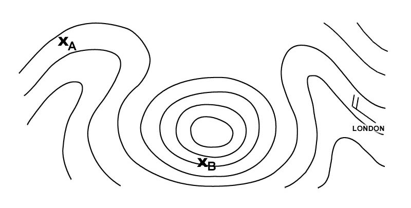 The information is carried by a modification of the frequency of the carrier.
 Frequency modulation consists of ?
Question 177-6 : A lf wave on an hf carrier wave a hf wave on an lf carrier wave an agreement between receiver and transmitter a system for interference elimination
 A lf wave on an hf carrier wave.
 Modulation is ?
Question 177-7 : The addition of information onto a radio wave during transmission the amplification of the received radio wave in the detector the separation of information from the radio wave during receiving the transformation of the radio wave into a digital signal
 The addition of information onto a radio wave during transmission.
 Skip distances are increased at night as ?
Question 177-8 : D layer disappears at night and the e and f layers are used instead d layer descends at a lower level reflection occurs earlier f layers disappears at night and the e layers is used instead the ionosphere becomes more ionized at night reflection will be stronger
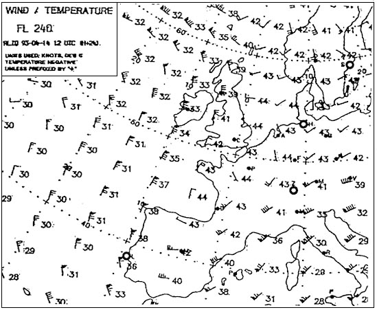 D-layer disappears at night and the e and f-layers are used instead.
 Which letter in the figure below indicates the 'ground wave' . 2561 ?
Question 177-9 : A b d c
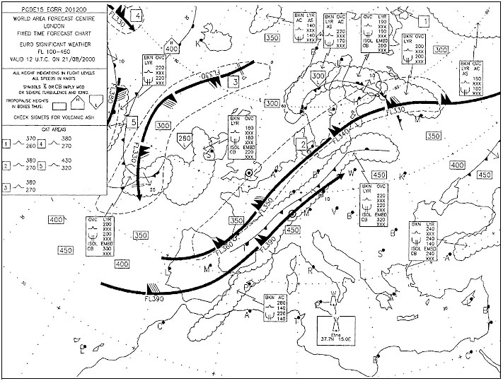 A.
A. A skip zone can be fin at letter s . 2561 ?
Question 177-10 : B and d a c and d d
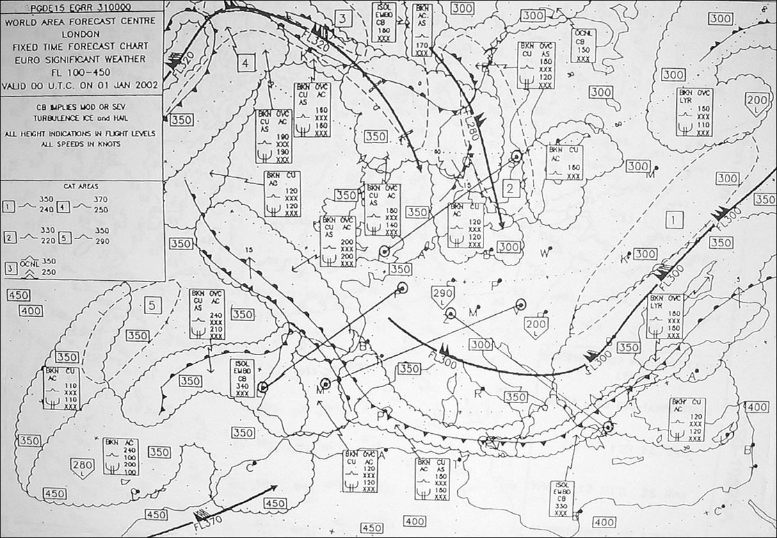 B and d.
 The vhf omnirange vor uses the following wavelengths ?
Question 177-11 : Metric decimetric hectometric centimetric
 Metric.
 Single side band ssb is used ?
Question 177-12 : In hf two way communication with transmissions of the meteorological aerodrome report metar in vhf transmissions to reduce transmission power in hf one way communication
 In hf two-way communication.
 What is meant by keying in a1a modulation ?
Question 177-13 : Interrupting the carrier wave to break it into dots and dashes interrupting the modulating signal to break it into dots and dashes changing the amplitude of the carrier wave to add information adding information on the carrier wave by use of a modulating signal
 Interrupting the carrier wave to break it into dots and dashes.
 Which of the following summaries lists only directional antennas ?
Question 177-14 : Loop antenna parabolic antenna slotted planar array antenna dipole antenna loop antenna parabolic antenna slotted planar array antenna dipole antenna sense antenna parabolic antenna helical antenna sense antenna parabolic antenna slotted planar array antenna helical antenna
 Loop antenna, parabolic antenna, slotted planar array antenna.
 In aviation electronic systems the so called doppler principle may be used in ?
Question 177-15 : Vor gps and mti and the turbulence mode of awr vor dme and gps vor dme and ils vor mti and the mapping mode of awr
 Vor, gps and mti and the turbulence mode of awr.
 A radio signal may be classified by three symbols in accordance with the itu ?
Question 177-16 : The first symbol indicates the type of modulation of the main carrier the three symbols together indicate which device is transmitting on the carrier the second symbol indicates the nature of information to be transmitted the third symbol indicates the nature of the signal modulating the main carrier
 The first symbol indicates the type of modulation of the main carrier
 Vhf very high frequency waves occur in which frequency range ?
Question 177-17 : 30 mhz – 300 mhz 3 ghz – 30 ghz 3 mhz – 30 mhz 300 mhz – 3000 mhz
 30 mhz – 300 mhz
 The skip zone is defined as ?
Question 177-18 : The area where neither the ground waves nor the sky waves are received the area where only the ground wave is receivable the area where ground and sky waves are receivable the area where only the sky wave is receivable
 The area, where neither the ground waves nor the sky waves are received.
 Which failure in radio navigation is connected with 'fading' ?
Question 177-19 : Twilight/night effect static discharge mountain effect shoreline/coastal effect
 Twilight/night effect
 The frequency of an airborne weather radar is 9 33 ghz what is the ?
Question 177-20 : 3 2 cm 32 m 3 2 m 32 cm
 3.2 cm
 What is the frequency of a radio wave with a wavelength of 8 25 m ?
Question 177-21 : 36 4 mhz 24 8 khz 36 4 khz 2 48 mhz
 36.4 mhz
 What is the simplest type of an antenna called ?
Question 177-22 : Dipole monopole loop antenna quadrupole
 Dipole
 What type of antenna is used in a modern airborne weather radar ?
Question 177-23 : Slotted planar antenna dipole omnidirectional antenna loop antenna
 Slotted planar antenna
 What happens to the amplitude and frequency of the carrier in a1a keying the ?
Question 177-24 : And the frequency both remain constant remains constant but the frequency increases increases but the frequency remains constant and the frequency both increase
 And the frequency both remain constant.
 Which aeronautical radio frequency band uses refraction within ionospheric ?
Question 177-25 : Hf vhf uhf vlf
 Hf
Hf The skip distance of hf transmission will increase with ?
Question 177-26 : Higher frequency and higher level of the refracting ionospheric layer lower frequency and higher level of the refracting ionospheric layer higher frequency and lower level of the refracting ionospheric layer lower frequency and lower level of the refracting ionospheric layer
 Higher frequency and higher level of the refracting ionospheric layer.
 The advantage of slotted antennas in modern radar technology is to… ?
Question 177-27 : Greatly reduce lateral lobes consequently concentrating more energy into the main beam produce a wide beam for better target detection eliminate the need for azimuth slaving simultaneously transmit weather and mapping beams
 Greatly reduce lateral lobes, consequently concentrating more energy into the main beam.
 Modulation is ?
Question 177-28 : The process of impressing and transporting information by radio waves a continuous wave which is capable of carrying audible signals without modification to allow the signal to be amplified to the required power level the process to provide a radio carrier wave for transmission
 The process of impressing and transporting information by radio waves.
 The unit for measuring frequency is and measures cycles ?
Question 177-29 : Hertz per second metres per minute metres per second hertz per minute
 Hertz, per second
 When raising the frequency of an electromagnetic wave the ?
Question 177-30 : Wavelength decreases wavelength remains the same wavelength increases wavelength and amplitude increases
 Wavelength decreases
 During a flight at fl210 a pilot does not receive any dme distance indication ?
Question 177-31 : Aeroplane is below the minimum altitude for line of sight propagation aeroplane is circling around the station the power of the transmitted signal is too weak to be received by the dme station altitude is too high
 Aeroplane is below the minimum altitude for line of sight propagation.
 Under what conditions can vhf voice communications often suffer interference ?
Question 177-32 : A temperature inversion in the atmosphere can cause 'super refraction' the interfering signal may be refracted from the ionosphere at night the interfering signal may be refracted from mountains between the transmitter and receiver the interfering signal may be refracted as a surface wave over a large expanse of water
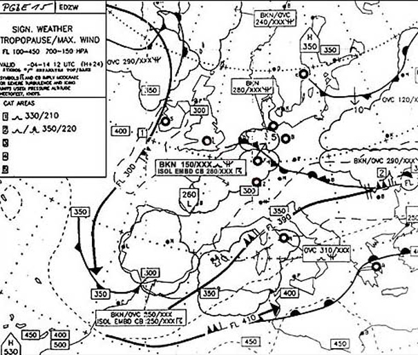 A temperature inversion in the atmosphere can cause 'super-refraction'.
 Pulse length is expressed as ?
Question 177-33 : Time an amplitude distance a frequency
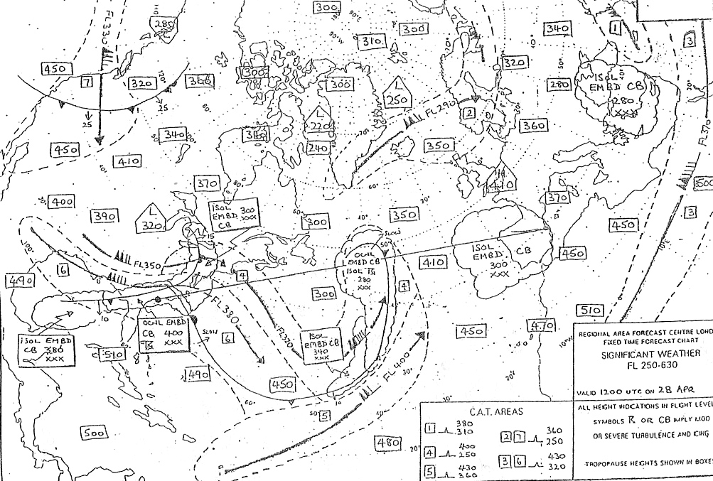 Time.
Time. Why do vhf radio signals used for communication and navigation have a limited ?
Question 177-34 : Because of the curvature of the earth ground waves are absorbed by the earth’s surface sky waves are refracted from the d layer direct waves interfere with ionosphere waves
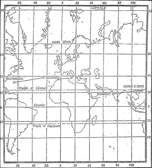 Because of the curvature of the earth.
 According to the international telecommunication union itu code a radio signal ?
Question 177-35 : Amplitude modulated by a speech signal such as is used for vhf com a continuous wave interrupted with a keyed morse code ident as used by an ndb amplitude modulated to transmit the morse code ident as is used by a vor interrupted to transmit the morse code identification as used by an ndb
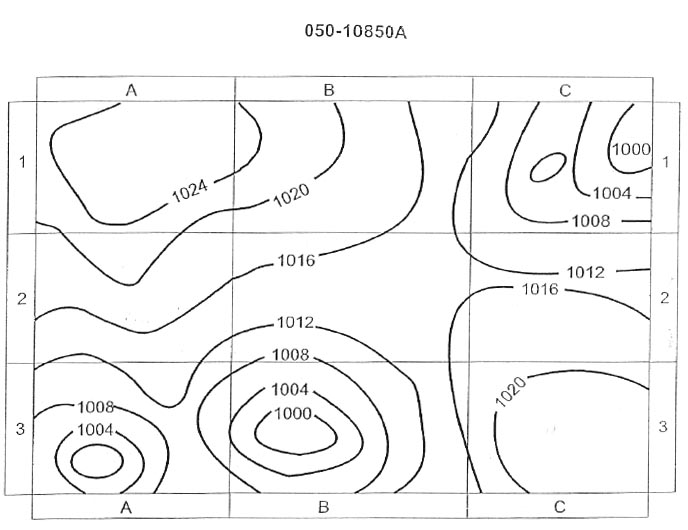 Amplitude modulated by a speech signal, such as is used for vhf-com.
 What does the term antenna shadowing mean ?
Question 177-36 : The antenna is masked from the transmitter due to the aircraft attitude the antenna shielded from the sun in order to reduce the influence of the ionosphere terrain is in between the receiver and the transmitter the antenna is placed under a dome
 The antenna is masked from the transmitter due to the aircraft attitude.
 What is the receiver aerial location of a gnss system ?
Question 177-37 : Top of the fuselage bottom of the fuselage left wing tip top of the tail
 Top of the fuselage.
 The following might be caused by antenna shadowing ?
Question 177-38 : Poor radio reception of a vor ident signal while the aircraft is making an orbit 360° medium level turn a weather radar failing to show a distant turbulent cloud due to the signals being blocked by a nearer cloud an aircraft appearing as two distinct indications on a radar controller's display blocking of a vor transmission caused by buildings close to the antenna
 Poor radio reception of a vor ident signal while the aircraft is making an orbit (360° medium-level turn).
 What is correct regarding antenna shadowing ?
Question 177-39 : Reduced reception by an antenna when part of the airframe blocks the signal to the antenna poor reception of gps signals due to very weak signals compared to the background noise at that frequency terrain blocking the path between the transmitter and receiver/aircraft antenna protection of a radar reception antenna from the strong signals produced by a nearby transmission antenna
The correct position for the gps antenna on an airplane is ?
Question 177-40 : On the top of the fuselage on the bottom of the fuselage in the nose of the aircraft in the tailplane
 On the top of the fuselage.
 ~
Exclusive rights reserved. Reproduction prohibited under penalty of prosecution.
7039 Free Training Exam
